Racing hat geschrieben:02.03., 19:48
Spending yet a few hours with the 60 today i decided to take it home for trials. In fact,me and the Mrs are listening to them both right now and..the whole thing works like a charm.
I´m none the less going to replace the main electrolytics as soon as possible. They ARE no matter what 50+yrs old and there´s no reason what so ever to become cheap here.
---- nicht übersetzt ----
Racing hat geschrieben:02.03., 19:48
I replaced the selenium rectifier for the heater circuit and that made the voltage for the preamp heating jump quite a bit. I now see 6.6VDC across each tube,which TBH is a TAD high why i´m going to implement a ceramic resistor of a few Ohms to make that drop to the set 6,3V.
Ich habe den Selengleichrichter für den Heizkreis ersetzt und das hat die Spannung für die Vorverstärkerheizung ziemlich viel hochschnellen lassen. 6,6VDC über jede Röhre finde ich ehrlich gesagt ein WENIG hoch, weswegen ich einen Keramikwiderstand mit ein paar Ohm einsetzen werde, um das auf 6,3V einzustellen.
Racing hat geschrieben:02.03., 19:48
Point here is that as the 60 uses pin 4+5 vs pin 9 that sets the given limit for the voltage needed. To be compared to how the 13 model is hooked,via pin 4 and 5 respectively.
A small issue to mark with the 60 is that due very intelligent application of the grounding of the system the actual negative pole of the heater-at the rectifier-is at a potential of (now) approx 6,6VDC negative. Ie; -6,6VDC.
This brings a potential vs the tubes "zero" that minimises the risk of interference.
Smart,to say the least.
Der Punkt hier ist dass der CSV60 Pin 4+5 gegen Pin 9 verwendet, der den Grenzwert für die benötigte Spannung setzt. Verglichen damit der CSV13, dort entsprechend mit Pin 4 und 5. Bemerkenswert am 60er ist durch die sehr intelligente Verwendung der Erdung des Systems der tatsächliche Negativpol der Heizung – am Gleichrichter – bei (-)6,6VDC liegt. Das führt zu einem Potential gegen den “Nullwert” der Röhre, was das Interferenz-Risiko minimiert. Smart – und das ist noch bescheiden formuliert.
Racing hat geschrieben:02.03., 19:48
Indeed the 60 is very well behaved,the little i´ve come to use it thus far (approx 2hrs so far). Just like you Jens i use these amps on a daily basis (surround) why reliability becomes imperative.
On the flipside..when components go belly up it isn´t the end of the world as these unit are very easy to work on.
In der Tat verhält sich der 60er sehr brav, so lang ich ihn bislang habe laufen lassen (2 Stunden bisher). Wie Jens lasse ich diese Verstärker täglich laufen (surround), wozu Verlässlichkeit unerlässlich ist.
Auf der anderen Seite...ist es nicht das Ende der Welt, wenn Bauteile den Geist aufgeben, den diese Geräte sind doch sehr wartungsfreundlich.
Racing hat geschrieben:02.03., 19:48
Temps.
I hear you. So in essence what is said,according to legend only,is that the real issue at hand would be the inner core temp of the transformers.?
Hm.
That..i honestly doubt to a point.
One amp that suffers from this,that is reknown,is the Vox AC-30. Older such often get "imploded" powertransformers. The uniform tell tale then being that they ALWAYS "sweat" before going bust.
You ALWAYS see paraffine and residue melting onto the amp chassis before this happens.
Temperaturen
Aha. Mal zusammengefasst, laut Hörensagen ist also das wahre Problem die Kerntemperatur der Übertrager?
Hm.
Ehrlich gesagt bezweifle ich das.
Ein Verstärker, der dafür bekannt ist, darunter zu leiden, ist der VOX AC-30. Ältere Exemplare weisen oft “implodierte” Übertrager auf, wobei gemeinhin gesagt wird, dass sie IMMER vorher “schwitzen, BEVOR sie futschgehen.
Man kann IMMER Paraffin und andere Rückstände auf das Chassis getropft sehen, bevor das passiert.
Racing hat geschrieben:02.03., 19:48
The 60 of mine..hm. Now,as i´ve touched on previously it about works and looks like factory fresh under the hood and around the removable lid. IOW it might be that i´m ill adviced to take to much into account seing what that CSV-60 has NOT seen as far as service.
That a more powerful amplifier by nature will produce more heat stands to reason,that is NOT my beef in this case..
Also granted that the actual amount of "free air" around especially the output transformers is minimised vs the CSV-13...agreed.
That is however NOT the same thing as the transformers are running TO hot.?
Mein 60er...hm. Nun, ich sagte es ja bereits: Er sieht fabrikfrisch aus unterm Deckel. In anderen Worten bin ich vielleicht doch schlecht beraten das darauf zurückzuführen, dass der CSV-60 noch nicht so viele Betriebsstunden gesehen hat.
Dass kräftigere Verstärker von Natur aus mehr Hitze produzieren liegt nahe, aber das ist NICHT mein Punkt hier...
Auch geschenkt, dass der wirkliche Freiraum besonders um die Ausgangsübertrager gegenüber dem CSV-13 minimiert ist – einverstanden.
Racing hat geschrieben:02.03., 19:48
Comparing the powertransformer to the CSV-13 ditto though..the 60 model is much more beefy. Not even on the same page,why i strongly doubt that Braun (through Klein&Hummel?) would miscalculate something like that.
Vergleicht man die Übertrager beim CSV-13 ebenso, dennoch...ist das 60er-Modell wesentlich kräftiger. Bezweifle ich doch stark, dass Braun (durch Klein&Hummel?) so etwas falsch berechnen würde.
Future will tell i gues.
Die Zukunft wird es zeigen, denke ich.
Racing hat geschrieben:02.03., 19:48
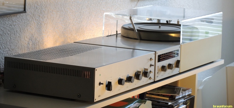
What remains now,here at home,is to either fabricate or purchase a wall suspended shelf system of sorts. My idea is to have one unit set per shelf and hence leave ample room for cooling. idea behind having it wall suspended is to leave the floor free from wires and what have you not (cleaning and so forth).
Was zu tun bleibt, hier zu Hause, ist ein wandhängendes Regalsystem zu kaufen oder selbst zu bauen. Die Idee hinter jedes Gerät einzeln auf einem Regalbrett zu haben ist genug Raum für Luftzirkulation lassen, das an-die-Wand-hängen lässt den Boden frei von Kabelgedöns und was-weiß-ich-noch alles (hilfreich beim Putzen usw.)
---- von hier an nix übersetzt ---- bis zum nächsten ---- ----
Racing hat geschrieben:02.03., 19:48
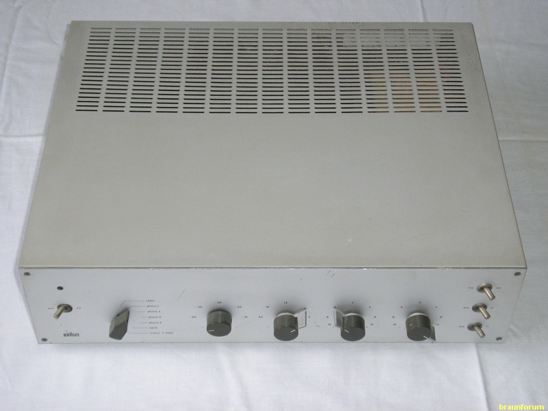
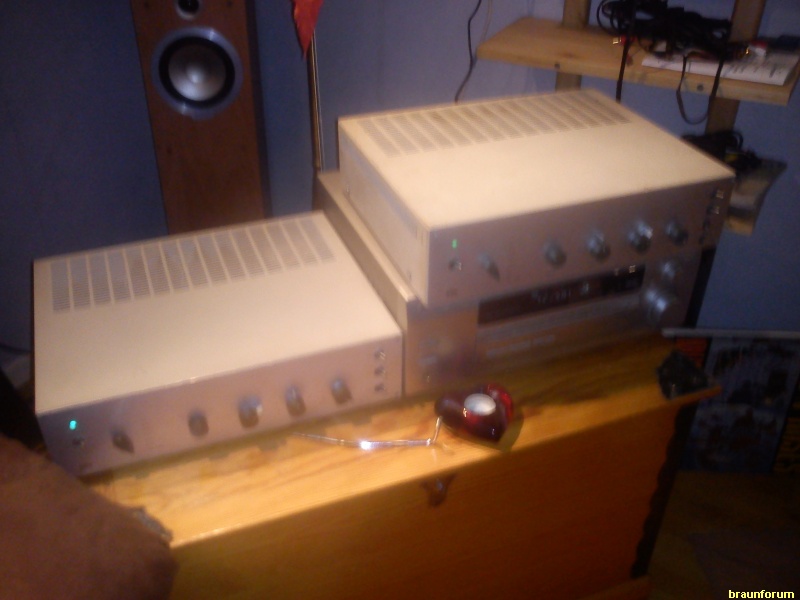
The old Pioneer receiver in the picture needs to be replaced too,and sorry to say i´d really like to see a receiver that lacks the transistor amplification bit-as i really don´t need it.
The receiver in case is only used for the onboard logics..that´s it. Ie; i use the receivers "preamp out" RCA connections to make it all happen and hence control the whole thing via the receiver remote control.
In the background of the picture you see my Tannoy floor speakers. These are currently complimented by a pair of Tannoy sattelite speakers out back but..i´m going to replace those as well in due time with a set of floor speakers too.
Right now i´m giving thought to a pair of old either Sonab or Carlsson "up sound" speakers from the mid -70´s.
Basically as the "rear" ones don´t really need to be directional IMO.
Well.
That much thus far. Going to snap yet a few pictures as i complete the overhaul completely of the 60 unit. So far...i´m a real happy camper at least!!
(Going to check temps no matter as time permits and will do so even tonight. Through my work with racecars i´ve got a digital pyrometer around the house too.. . No...juuuuuust...no..don´t ask )
---- Ende nicht übersetzt ----
Racing hat geschrieben:02.03., 20:45
Oh.
About forgot.
I adjusted anode loss in idle to 34mA@358VDC.
Oh. Fast vergessen. Ich habe den Anodenstromverlust auf 34mA bei 358VDC eingestellt.
Racing hat geschrieben:03.03., 23:04
Well Jens,that sure is a sight for sore eyes!!
Congrats on a really nice looking,and sounding,setup. Look like a million dollars!
Yes. I figured as much that my 60 was a later revision. Some of the caps i removed were stamped 9/64. Kind of tells the story i guess.
Nun, Jens, was für ein Anblick für meine trüben Augen! Glückwunsch zu einem wirklich schön aussehenden und klingenden Ensemble. Sieht aus wie ein Hauptgewinn!
Ja, ich habe mir auch schon gedacht dass mein 60er eines der späteren Modelle war. Einige Kondensatoren, die ich entfernt habe, trugen 9/64-Stempel. Das erklärt einiges.
---- von hier an nix übersetzt ---- bis zum nächsten ---- ----
Racing hat geschrieben:03.03., 23:04
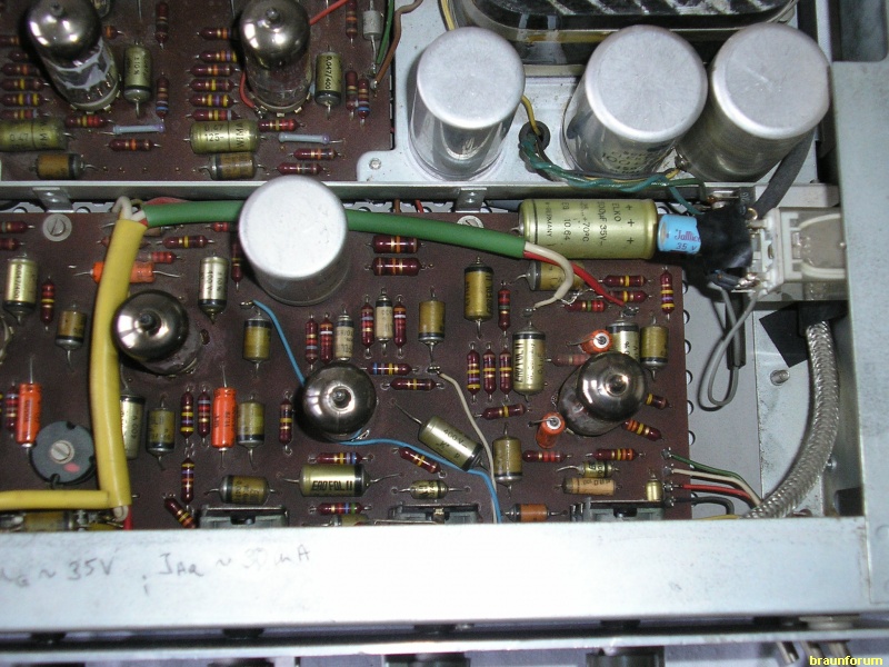
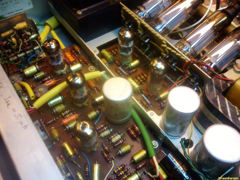
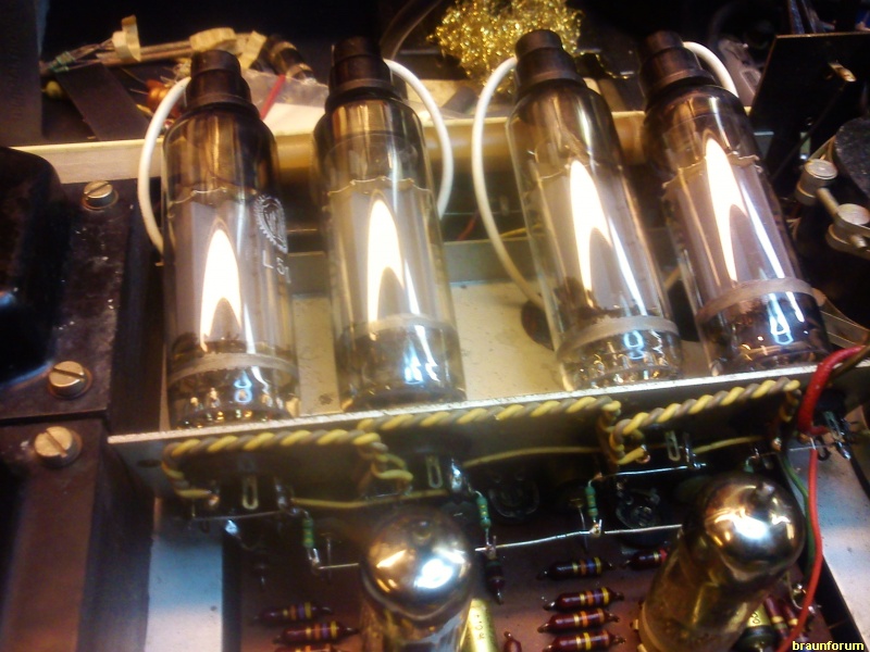
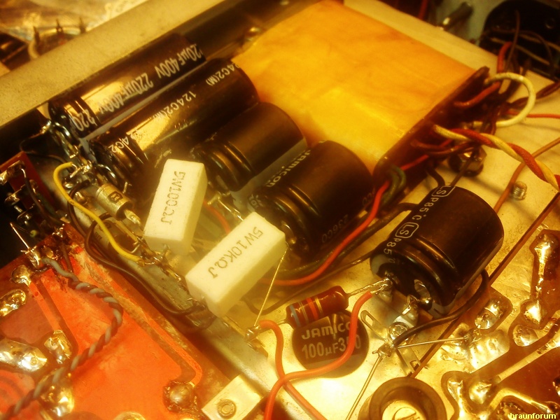
Took the 60 with me to the shop again today and replaced everything electrolytic in sight. Add to that that i upped capacitance somewhat for the first hit,and as well for the preamp. The OEM 32uF+32uF cap was replaced by a pair of snap-in of 100uF each.
In turn all of the cathode decoupling ones for the preamp were replaced.
In turn i unbolted the bracket for the powertubes and replaced the two e-lytes for the bias circuit,and here i upped capacitance in a more severe manner,ending up with 2*100uF.
My 60 in turn differed a bit as far as the pentode side of the phaseinverters vs the schematic.
The 2uF cap in the schem for the screen was IRL 470nF. A move that makes the pentode side amplify LESS of the lower frequencys. Replaced that with 1uF e-lytes.
In turn i replaced all of the poly/signal caps while at it. Fresh components all around as far as the PI PCB in short. (Resistors are still stock though)
As for the rectified heater system for the preamp in turn. Remedy for the slightly to high voltage after replacement of the diode setup was simple. I just hooked a 1 Ohm/1w resistor between the rectifier positive and the preamp PCB. Made me end up at 6.3VDC sharp. Done deal.
Amp has followed me home again and..what can i say? It works a friggin million bux worth!
Sound is just mindblowing! It is THAT good. As far as tonal difference vs the CSV-13/1..nah. Not really. Not IMO at least,mind you though...thus far we´re talking "normal" TV volumes in this case.
What´ll happen as i play a vinyl record..remains to be seen.
What i haven´t done to either of the two units is replace any of the poly caps in the preamps.
Maybe one should look into that? Point being that albeit the caps in case doesn´t leak they can sure have drifted a whole lot over the last 50yrs..?
Anyways.
I hope the small tidbits of info i´ve presented can be of use to someone. Like..the silicon swap for rectification of the preamp heaters and how to handle the increased voltage.
Speaking of which. All said and done,and with fresh capacitance in place,i ended up at 359VDC with all 4 powertubes set to 32mA. (mind you this is with 1 Ohm cathode resistors-Ie,it incl anode and screen consumption both)
Oh!
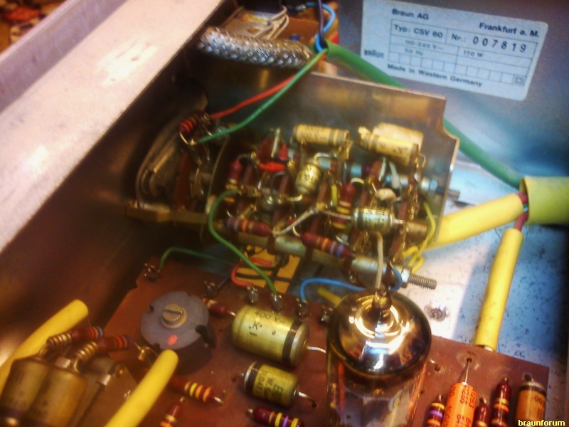
Pulled yet another trick that IS of importance.
None of these amps comply to "the golden rule". That is..that the grounding of the first hit electrolyte should be routed to bridge negative (or centertap for that matter when applicable).
My CSV-60 did NOT comply to "the golden rule",and if you observe the above picture you will see that i´ve routed the two germanium diodes quite different vs stock. Indeed the second diode now runs directly to the solderprong where the second 220uF electrolyte hits the chassis,and...indeed this has made the amplifier very very very silent in idle.
A small,but imperative,little "modification" that needs to be adhered to IMO.
To sum it up.
Absolutely NOTHING is to be let to come between in this case the bridge negative and the grounding of that first series of electrolytes.
Racing hat geschrieben:04.03., 03:47
Well...that brought a smile to my face
Never thought the other way around,that some might have issues with english. Sorry..
Very neat of you to translate though Jens,and to be honest i believe you´re doing a WAY better job than would i ever.
Felt real funny reading my own text in German however..
(´N yes..i guess the Austrovox part can be left out for the sake of argument )
---- Ende nicht übersetzt -----
Racing hat geschrieben:04.03., 03:47
As for the "handwarm"...now this is just none evidence based opinion and what´s more after a mere 1st evening of running in its new enviroment and with fresh parts...
But by using the same measure you do i´m here to tell you that on the outside the CSV-13/1 of mine and the CSV-60 feels about the same temperature.
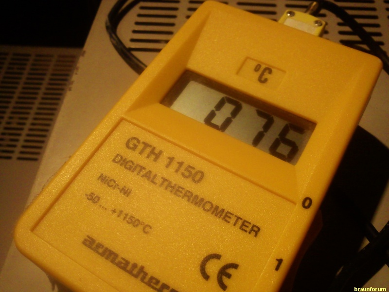
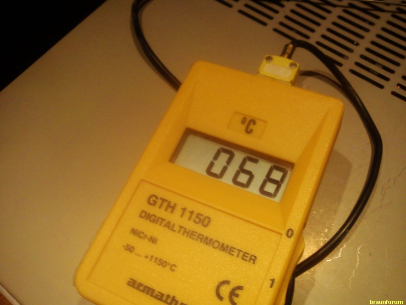
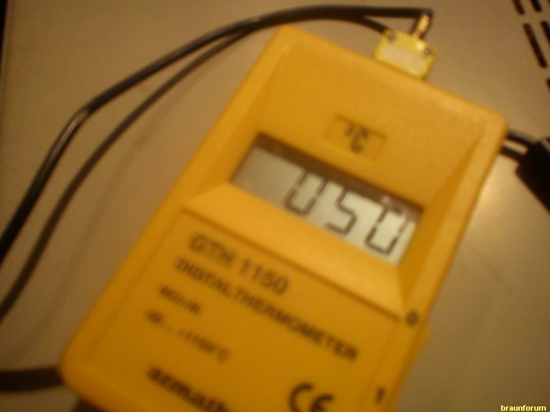
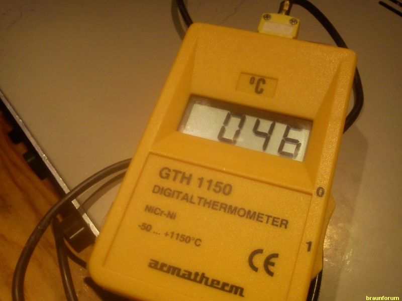
But..having settled here at home i AM going to bring that pyrometer to it. Got two of them.
First of all one "of the real thing". Ie;a type K element based unit that we use to develop engines.
Then..the second one is simply one of the cheap laser ones.. My thinking here being that you could point the laser through the louvers of the chassis directly onto the transformer cores.
Thus far though?
Amps,in tandem,sounds absolutely lovely. Simple as that.
Was “handwarm” angeht – das ist nur eine Meinung (Mutmaßung), die nicht auf harten Fakten basiert, und das nach lediglich dem ersten Abend Betrieb in neuer Umgebung und mit frischen Bauteilen.
Aber unter Verwendung der gleichen Messmethode wie Du kann ich sagen, dass sich die Temperatur außen am Gehäuse bei meinen CSV 13/1 und dem CSV 60 ungefähr gleich anfühlt.
*** Erinnert mich an das „Mamameter“(English equivalent: „mometer“): Meine Mutter, die durch Handauflegen immer direkt wusste, ob ich Fieber habe oder nicht – und dann entsprechend doch zur Schule musste…***
Aber das prüfe ich noch nach mit zwei Messgeräten.
[...]
Was bleibt noch zu sagen?
Die Verstärker, hintereinander, klingen absolut klasse. So einfach ist das.
So, das war noch im Arbeitsspeicher, mehr gibbet nich.
Gruß, Gereon